CVE20003, Design of Concrete Structures Project 2B Sem2, 2025-26 | Swinburne
CVE20003, Design of Concrete Structures
Project 2B – Design of a multistorey concrete building Semester 2, 2025-26
Due date: Individual project
Weighting: 15% A multistorey building
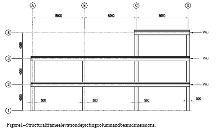
A multistorey building is to be designed and constructed in Melbourne’s eastern suburbs. A preliminary assessment by the engineer has nominated that a concrete framed building would be most suitable. The engineer has nominated the geometry of the structure as per figures 1-3 below.
The beams and columns will be rigidly connected using steel reinforcement and should be designed as a moment resisting frame to resist the horizontal forces which will be imposed on the structure due to wind actions (Wu) in the locations shown in figure 2. The columns are connected into rigid footings at their base so footing to column connection can be assumed as fixed for design purposes. All column cross section dimensions should be taken as 500mm x 500mm square in cross section. Each level is to be designed for activity/occupancy type E, (warehousing and storage areas) assuming specific use of mobile stacking with a stacking height of 3.0m (classification E in AS1170.1 table 3.1).
After analysis by the engineer, superimposed dead load (SDL) including finishes is to be taken as 1.0 kPa and the self-weight of the beams and columns should be determined and included as part of the dead load. A wind loading analysis conducted by the engineer has determined that a constant positive wind load of (Wu) of 200 kN at each level.

Figure 1 – Structural frame elevation depicting column and beam dimensions

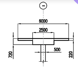
Figure 2 – Section 1, typical cross section of horizontal beam elements