Instructions: This is an individual assignment. Do not discuss your solution with anyone else. Attempt all the five This assignment carries 50% weight towards the final marks for this course. The deadline for submitting the completed assignment is 14 Nov 2025 (Friday). Late submission (without valid reasons) will attract penalty. After you have completed your …
Continue reading “MA7131 Finite Element Method Individual Assignment 2 Semester 1, AY2025/2026 – NTU Singapore”
The post MA7131 Finite Element Method Individual Assignment 2 Semester 1, AY2025/2026 – NTU Singapore appeared first on My Assignment Help SG.
Instructions:
- This is an individual assignment. Do not discuss your solution with anyone else.
- Attempt all the five This assignment carries 50% weight towards the final marks for this course.
- The deadline for submitting the completed assignment is 14 Nov 2025 (Friday). Late submission (without valid reasons) will attract penalty.
- After you have completed your assignment, slide in your assignment papers under my (lecturer’s) office door at N3-02c-78 by 14 Nov 2025 (Friday). After collecting your assignment, the lecturer will acknowledge the receipt by email. Double check my office number (N3-02c-78) displayed on my office door before you slide in your papers.
- If you think any quantity or numerical value is not specified in any of the questions, assume a suitable numerical value or treat it as a parameter. However, state this clearly in your solution.
- You are encouraged to use software packages such as MATLAB or Wolfram Alpha to aid your calculations/derivations. However, you should show the details of your derivations/solution/ coding in your assignment, and not just simply present the final answers/results from the software.
- Study the lecture slides of relevant topics/chapters before attempting to solve the problems. Do not attempt to solve the problems purely based on common sense or your prior knowledge gained from other courses. Use the methods/techniques taught in this course to solve the problems.
- Show all your steps clearly. Steps carry marks. If you do not show steps, you will lose marks.
cta_question_1
————————————————————————————————————————–
Questions
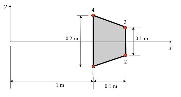
1. Figure 1 shows an axisymmetric solid where y-axis is the axis of symmetry and the cross-section is a trapezium. The cross-section is modelled as a single 4-node quadrilateral isoparametric element as shown.

Figure 1
The radial displacements in metres (along x-axis) of nodes have been determined to be 0.001,
9.6811×10⁴, 9.6811×10⁴ and 0.001, for nodes 1,2, 3 and 4, respectively. The axial displacements
in meters (along y-axis) are 2.5964×10⁵, 1.4188×10⁵, 1.4188×10⁵ and 2.5964×10⁵, respectively. The Young’s modulus of the material is 200 GPa and the Poisson’s ratio is 0.3.
(a) Using B-matrix and generalized Hook’s Law, determine the strain and stress components at all the 2×2 Gauss point locations. Thereby determine the strain energy stored in the element by 2×2 Gaussian integration.
(10 marks)
(b) Determine the mass moment of inertia Iyy by 2×2 Gaussian integration. (Obtain the necessary formula Iyy by referring to books or internet. Cite references.) Take the mass density to be 7850 kg/m3.
(10 marks)
2. Figure 2(a) shows a 4-node quadrilateral isoparametric element. The nodal coordinates of the element in physical space as (x1, y1) = (0, 0), (x2, y2) = (1, 0), (x3, y3) = (1, 1) and (x4, y4) = (0, 1). These coordinates correspond to a square (un-distorted) element shape. Now, let us introduce element shape distortion as shown in Figure 2(b) by redefining the nodal coordinates of nodes 2 and
4 as (x2, y2) = (1s, 0) and (x4, y4) = (0, 1s) where s is a real parameter: 1< s <2. (The shape of the element in the local coordinate space is a square as usual.)
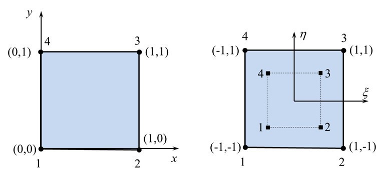
Figure 2(a)
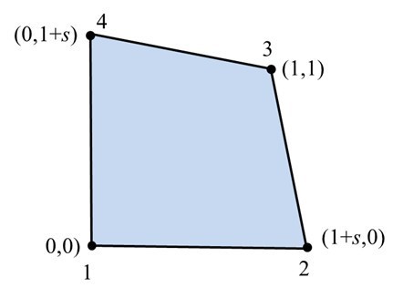
Figure 2(b)
It is intended to study for what values of s (both positive and negative), the value of |J| becomes zero within the element as well as outside the element. Obtain an expression for |J| in terms of s, and . For typical values of s (chosen by you), draw contour lines in the - plane along which |J| is zero.
(20 marks)
3. Figure 3 shows a uniform beam AB of length L = 1 m and bending rigidity EI = 105 Nm2 fixed to a rigid wall at end A. There are three pairs of ‘hooks’ and ‘eyes’ as shown. EOF is a rigid beam (and can only undergo rotational motion about O). The distance EO is twice of OF. The two springs shown have the same stiffness k = 5×10⁵ N/m. The three hooks are assembled onto the hooks gently. Model the beam using a single 2-noded beam element having two degrees of freedom per node (i.e., vertical displacement and cross-sectional rotation).
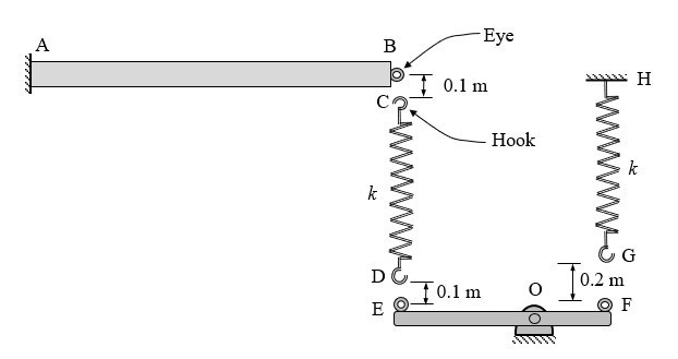
Figure 3
First, assemble the element stiffness matrices to obtain the global equations (for the assembly). Then, apply the boundary conditions associated with supports at A and H using the elimination method. Then apply the multi-point contraints (associated with the assembling of hooks with the eyes) by penalty method. Choosing appropriate values for the penalty constants, solve the resulting equations for the vertical displacement of the beam at B so that the displacements are accurate up to 4 significant figures.
(20 Marks)
4. Consider the problem of steady state heat conduction through a framed structure (see Figure 4) consisting of 11 beam members of equal length of 1 m and cross-sectional area 0.01 m2 with all members joined together by welding. The (acute) angle between any two beam members is 60 degrees. For the finite element modelling, you are required to use a single 2-node (linear) heat conduction element to model each beam member. Joint A is at a constant temperature of 100 oC while joint D is at 50 oC. Each rod gains heat from the surrounding at the rate of 100 W/m (heat source). Take the thermal conductivity of the rod material as 100 Wm-1 oC -1.
Determine the nodal temperatures of the framed structure. Determine how much heat enters/leaves the structure through joints A and D. Also determine the heat flow rate and direction in each rod.
Show all these results pictorially on a neat sketch of the framed structure.
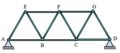
Figure 4
(20 Marks)
5. Figure 5 below shows a structure made up of a straight uniform beam AB of length 2 m, bending rigidity EI = 105 Nm2 and mass 40 kg connected to a solid disc of mass 100 kg, radius 0.1 m2 and thickness 0.01 m. The lengths portions AB and BC are equal, and each of these portions is to be modelled by a single beam element having two degrees of freedom per node (i.e., vertical displacement and cross-sectional rotation).
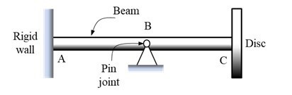
Figure 5
Use HRZ lumped mass matrix for the beams. Write the stiffness and mass matrices for the finite elements, assemble them to obtain the system (stiffness and mass) matrices, apply the boundary conditions to reduce the size of the these matrices, and thereby write the eigenproblem for the free vibration analysis of the structure.
Solve the eigenproblem to find an estimate of the smallest natural frequency (in Hz) of the structure accurate up to 4 significant figures by performing inverse iterations using a starting vector whose entries are all equal to unity.
(20 marks)
End of Paper
cta_question_2
The post MA7131 Finite Element Method Individual Assignment 2 Semester 1, AY2025/2026 – NTU Singapore appeared first on My Assignment Help SG.